

DCI Formats in 5G NR
In 5G-NR, efficient radio resource scheduling is essential for achieving high throughput, low latency, reliable communication, and efficient utilization of available spectrum. One of the most important mechanisms enabling this scheduling is DCI, transmitted by the gNB to UE over the Physical Downlink Control Channel (PDCCH).
DCI provides the control instructions required by the UE to receive downlink data, transmit uplink data, handle HARQ retransmissions, adjust transmission power, and respond to various network scheduling decisions.
Unlike user-plane data carried over PDSCH or PUSCH, DCI primarily communicates scheduling and physical-layer control information.
5G NR supports multiple DCI formats, each designed for specific scheduling requirements. These range from basic uplink and downlink grants to advanced features involving MIMO, bandwidth part switching, slot format indication, power saving, multi-cell scheduling, and multicast transmission.
What Is Downlink Control Information (DCI) in 5G NR?
Downlink Control Information is a structured physical-layer control message transmitted by the gNB on PDCCH.
Although DCI is always transmitted in the downlink direction, it can control both uplink and downlink communication.
For example, when the gNB wants to schedule a downlink transmission, it transmits a DCI containing the allocated radio resources and relevant transmission parameters. Similarly, when the UE needs to transmit uplink data using a dynamically scheduled grant, the gNB can issue the corresponding uplink DCI.
Function of DCI
The main functions of DCI include:
- Downlink scheduling: Allocating radio resources for PDSCH transmission.
- Uplink scheduling: Granting resources for PUSCH transmission.
- Modulation and coding control: Indicating the Modulation and Coding Scheme (MCS).
- HARQ management: Identifying HARQ processes and controlling new transmissions or retransmissions.
- Power control: Providing Transmit Power Control (TPC) commands.
- MIMO and antenna configuration: Controlling selected transmission parameters, antenna ports, and precoding where applicable.
- Bandwidth Part (BWP) switching: Supporting dynamic changes between configured BWPs.
- Slot format signaling: Indicating applicable downlink, uplink, and flexible symbol configurations.
- Advanced radio features: Supporting pre-emption, power-saving signaling, multi-cell scheduling, sidelink, and multicast/broadcast services.
The key concept is that DCI acts as an instruction message between the gNB scheduler and the UE physical layer. The gNB determines the resources, while the UE interprets the DCI and performs the corresponding transmission or reception.
How DCI Works with PDCCH, PDSCH and PUSCH
DCI is transported over PDCCH, which is mapped to the configured Control Resource Set (CORESET). The UE monitors configured search spaces and attempts to decode PDCCH candidates to determine whether a control message is intended for it.
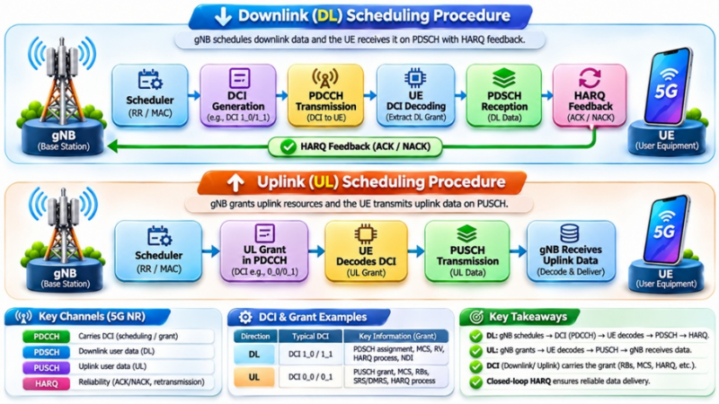
Consider a practical downlink example.
The gNB determines that a UE should receive data using 20 Physical Resource Blocks (PRBs), a particular MCS, and a specified HARQ process.
The gNB transmits an appropriate DCI format, such as DCI 1_1, containing the scheduling information. After decoding the PDCCH, the UE determines which frequency resources and OFDM symbols contain its scheduled PDSCH.
The UE then demodulates and decodes the corresponding PDSCH transmission and provides HARQ acknowledgement information according to the configured feedback procedure.
DCI therefore establishes the relationship between the scheduler decision and the actual physical-layer data transmission.

DCI Transmission and Processing in 5G NR
Before DCI is transmitted over PDCCH, several processing operations are performed.
DCI payload generation
The gNB first prepares the DCI payload containing fields applicable to the selected format.
These may include frequency-domain assignment, time-domain assignment, MCS, HARQ process number, redundancy version, and power control information.

The number and size of fields depend on the DCI format and the UE’s higher-layer configuration.
CRC attachment
A 24-bit Cyclic Redundancy Check (CRC) is attached to the DCI payload.
In LTE, PDCCH DCI uses a 16-bit CRC, while NR uses a 24-bit CRC. This provides stronger error detection for NR control signaling.
The relevant portion of the CRC is scrambled using a Radio Network Temporary Identifier (RNTI), allowing the UE to validate the control message against an expected identity.
Importantly, the RNTI is not simply transmitted as a separate address field inside every DCI payload. Its use in CRC scrambling is central to identifying the intended recipient or purpose.
Polar coding and rate matching
After CRC attachment, DCI undergoes channel coding using Polar codes.
The encoded bits are rate-matched to fit the available PDCCH resources before being scrambled, modulated, and mapped onto physical resources.
PDCCH resource mapping
PDCCH transmission uses one or more Control Channel Elements (CCEs).
The supported aggregation levels are:

One CCE consists of six Resource Element Groups (REGs), with each REG corresponding to one PRB over one OFDM symbol.
A higher aggregation level allocates more coded resources to PDCCH and can improve decoding reliability, at the cost of greater control-channel resource consumption.
For example, a UE experiencing challenging radio conditions may require a higher aggregation level than a UE operating with favorable channel quality.
However, aggregation-level selection is a scheduler implementation decision and depends on available PDCCH resources, link adaptation, and other network constraints.
Understanding CORESET and Search Space
Two important concepts associated with DCI reception are CORESET and Search Space.
CORESET defines the time-frequency region in which PDCCH may be transmitted. It specifies the allocated frequency resources, the number of OFDM symbols, and relevant CCE-to-REG mapping parameters.
Search Space defines when and where the UE monitors possible PDCCH candidates within an associated CORESET. It includes monitoring periodicity, offset, monitored symbols, aggregation levels, and candidate counts.
5G NR supports two major categories:

During initial access, the UE uses common search-space configurations to receive essential control information before dedicated scheduling is established.
After RRC configuration, UE-specific search spaces can be used to monitor more advanced scheduling formats.
A UE does not blindly decode every possible DCI format in every slot. Its monitoring behavior is determined by applicable configuration and 3GPP-defined limits.
Complete List of DCI Formats in 5G NR
3GPP TS 38.212 Release 19 defines 24 DCI formats across five major categories.
Uplink scheduling DCI formats

DCI Format 0_0: Fallback Uplink Scheduling
DCI format 0_0 is primarily used for scheduling PUSCH transmission in one serving cell.

It is considered a fallback format because it supports relatively simple scheduling with fewer configuration-dependent fields compared with enhanced formats.
DCI Format 0_1: Enhanced Uplink Scheduling
DCI format 0_1 provides advanced uplink scheduling capabilities beyond the fallback format.
It supports additional fields associated with more flexible resource allocation, MIMO transmission, SRS triggering, and uplink control.

Important additional fields
- Bandwidth Part Indicator: Allows selection of a configured uplink BWP when applicable.
- Carrier Indicator: Supports cross-carrier scheduling where configured.
- Precoding Information and Number of Layers: Provides transmission parameters for codebook-based uplink MIMO.
- SRS Resource Indicator (SRI): Indicates the relevant SRS resource or resources according to the configured uplink transmission scheme.
- SRS Request: Can trigger aperiodic Sounding Reference Signal transmission.
- CSI Request: Supports triggering applicable aperiodic CSI reporting.
- UL-SCH Indicator: Determines whether uplink shared-channel data is included in the scheduled PUSCH under supported conditions.
Importance for MIMO testing
DCI 0_1 is particularly useful when analyzing uplink MIMO.
For example, in codebook-based PUSCH transmission, the precoding information and number-of-layers field helps determine the transmission rank and applicable precoder selection.
In non-codebook-based PUSCH transmission, the configured SRS resources and relevant SRI interpretation become important.
An important distinction: DCI 0_1 does not, by itself, establish whether a system uses codebook-based or non-codebook-based uplink transmission. The RRC-configured PUSCH transmission scheme and SRS configuration must also be examined.
DCI Format 0_2: Compact and Configurable Uplink Scheduling
DCI format 0_2 supports PUSCH scheduling with configurable field sizes.
It was introduced as part of NR physical-layer enhancements aimed at supporting more flexible and latency-sensitive scheduling requirements.
Compared with conventional enhanced grants, DCI 0_2 can provide a more compact control structure, depending on its configuration.
This makes it relevant to implementations where control signaling overhead and scheduling flexibility are important.
The network may configure parameters such as field bit widths and associated scheduling options through higher-layer signaling.
However, a smaller DCI payload does not automatically guarantee lower end-to-end latency. The actual benefit also depends on monitoring opportunities, scheduling behavior, processing time, and radio conditions.
DCI Format 0_3: Advanced Multi-PUSCH Scheduling
DCI format 0_3 expands uplink scheduling functionality by supporting scheduling of one or more PUSCH transmissions within a cell or across multiple cells, according to the configured operation.
Its main advantage is the ability to support more sophisticated scheduling scenarios without relying exclusively on separate conventional grants for each transmission.
Potential benefits include more efficient control signaling and improved coordination of scheduled transmissions.
This format becomes particularly relevant in advanced carrier-aggregation and 5G-Advanced scheduling scenarios.
Downlink scheduling DCI formats

DCI Format 1_0: Fallback Downlink Scheduling
DCI format 1_0 is used for scheduling PDSCH transmission and plays an essential role during initial access and common network procedures.


DCI 1_0 during 5G SA initial access
Step 1 — SIB1 reception: The UE identifies a PDCCH carrying DCI 1_0 addressed through SI-RNTI. This schedules the PDSCH carrying SIB1.
Step 2 — Random access response: After transmitting Msg1, the UE monitors the configured random-access search space. The gNB may transmit DCI 1_0 addressed using RA-RNTI, scheduling the PDSCH containing the Random-Access Response.

Step 3 — Msg3 transmission: The UE uses the uplink grant carried within the Random-Access Response MAC message to transmit Msg3.
This is an important distinction: the Msg3 grant in a four-step random-access procedure is carried in the MAC RAR, not necessarily as a separate PDCCH DCI 0_0 grant.
Step 4 — Contention resolution: During the applicable contention-resolution procedure, DCI 1_0 addressed using TC-RNTI can schedule the relevant downlink transmission.
Once access is successfully completed, the UE can proceed with its assigned C-RNTI and applicable dedicated scheduling.
DCI Format 1_1: Enhanced Downlink Scheduling
DCI format 1_1 is widely relevant to advanced 5G NR downlink scheduling.
It offers greater flexibility than fallback DCI 1_0 and supports features associated with MIMO operation, CSI, beam-related parameters, and sophisticated resource allocation.
DCI Format 1_2: Compact Downlink Scheduling
DCI format 1_2 supports PDSCH scheduling using configurable field sizes.
Like uplink DCI 0_2, it is relevant to applications where flexible control signaling and reduced scheduling overhead are desirable.
Its configuration can support compact scheduling for latency-sensitive transmissions, subject to the overall radio implementation.
The UE must be configured to monitor the appropriate format and interpret its fields correctly.
DCI Format 1_3: Advanced Multi-PDSCH Scheduling
DCI format 1_3 provides advanced downlink scheduling functionality involving one or more PDSCH transmissions in one cell or multiple cells, according to the configuration.
This can reduce the need for repeated individual scheduling messages in suitable scenarios.
It is particularly relevant to enhanced carrier aggregation and advanced scheduling mechanisms.
The main engineering requirement is that the UE correctly interprets the scheduled-cell information, allocation parameters, and applicable HARQ behavior for the multiple transmissions.
DCI Format 2_0: Slot Format Indication
DCI format 2_0 is used for group-common control signaling involving slot format information and other applicable indications.
Its CRC is scrambled using SFI-RNTI.
In TDD networks, the scheduler must coordinate downlink, uplink, and flexible symbol usage.
The slot format can identify symbols as:
- D — Downlink
- U — Uplink
- F — Flexible

For example, a configured slot-format combination may include a pattern such as:
D D D D D D D D F F U U U U
This is an illustrative 14-symbol pattern, not a universal slot configuration.
DCI 2_0 can provide dynamic slot-format indications within the constraints of higher-layer configuration.
It does not arbitrarily override every semi-statically configured symbol direction. The applicable rules and restrictions are defined in TS 38.213.
In later releases, DCI 2_0 also supports additional group-common indications involving resources and related control functions.
DCI Format 2_1: Downlink Pre-emption Indication
DCI format 2_1 is associated with downlink pre-emption notification.
Its CRC is scrambled using INT-RNTI.
Consider a UE receiving an ongoing eMBB transmission. The gNB may need to transmit latency-critical traffic using resources that overlap with a previously scheduled transmission.
DCI 2_1 allows the network to notify affected UEs about PRB and OFDM-symbol regions where they may assume that no intended transmission for them was present.
This helps the receiver handle the affected resources appropriately.
The mechanism is important for scenarios requiring coexistence between conventional broadband traffic and latency-sensitive traffic.
DCI Format 2_2: PUSCH and PUCCH Power Control
DCI format 2_2 provides group-based power-control commands for PUSCH and PUCCH transmissions.
It uses applicable TPC-related RNTIs, including:
- TPC-PUSCH-RNTI
- TPC-PUCCH-RNTI
Transmit Power Control is important for maintaining reliable uplink performance while limiting unnecessary interference and power consumption.

For example, under the conventional accumulated 2-bit TPC mapping, the adjustments are:
This mapping applies to the relevant accumulated TPC operation and must not be generalized to every PUSCH power-control mode.
DCI Format 2_3: SRS Power Control
DCI format 2_3 provides group-based TPC commands for Sounding Reference Signal transmissions.
It uses TPC-SRS-RNTI and may contain SRS request information under applicable configurations.
SRS allows the gNB to estimate relevant uplink channel characteristics.
This information can support uplink scheduling, link adaptation, precoding decisions, and TDD-based channel sounding operations.
For SRS-based beamforming and MIMO verification, engineers should correlate the configured SRS resources, trigger mechanisms, measured channel quality, and applicable transmission power behavior.
Additional DCI Formats Introduced in Later NR Releases
The original 5G NR DCI set has been expanded to support additional radio capabilities.
DCI 2_4 — Uplink Cancellation Indication
DCI 2_4 notifies affected UEs about scheduled uplink resources whose transmission must be cancelled according to the applicable cancellation indication.
This mechanism supports situations where higher-priority uplink traffic requires the network to reclaim resources.
The relevant CRC is scrambled using CI-RNTI.
DCI 2_5 — Soft Resource Availability
DCI 2_5 signals the availability of configured soft resources.
Its use is associated with advanced radio coordination mechanisms, including integrated access and backhaul-related resource operation.
It uses AI-RNTI, where AI refers to Availability Indication in this context, not Artificial Intelligence.
DCI 2_6 — Power-Saving Indication
DCI 2_6 provides power-saving information outside DRX Active Time.
It can support wake-up-related control and help the UE avoid unnecessary PDCCH monitoring under applicable configurations.
This contributes to efficient UE energy consumption.
DCI 2_7 — Paging Early Indication
DCI 2_7 supports paging early indication and Tracking Reference Signal (TRS) availability information.
These mechanisms can improve power-efficient paging-related operation by allowing the UE to use configured indications before performing further reception procedures.
DCI 2_8 — Aperiodic Beam Indication
DCI 2_8 supports aperiodic beam indication and associated time-resource signaling.
This enhances the flexibility of beam-related control in advanced NR operation.
DCI 2_9 — Network Energy-Saving Control
DCI 2_9 supports signaling associated with cell Discontinuous Transmission (DTX), cell Discontinuous Reception (DRX), and related network energy-saving operations.
Release 19 also includes applicable primary-cell energy-saving mode indications and synchronization-signal periodicity adaptation.
This format reflects the increasing importance of energy efficiency in 5G-Advanced networks.
DCI Formats 3_0, 3_1 and 3_2: Sidelink Scheduling
Sidelink enables direct communication between devices in supported scenarios without requiring every user-data transmission to pass through the conventional gNB-to-UE radio link.
DCI 3_0 supports scheduling of NR sidelink transmission, while DCI 3_1 is associated with LTE sidelink scheduling.
DCI 3_2 supports scheduling related to NR sidelink Positioning Reference Signals.
These formats are relevant to supported sidelink operations, including applications involving vehicle communications and positioning.
They should not be confused with Sidelink Control Information (SCI), which is transmitted over the sidelink radio interface.
DCI Formats 4_0, 4_1 and 4_2: Multicast and Broadcast
5G NR also supports multicast and broadcast service-related scheduling.
The 4_x DCI family supports PDSCH scheduling for applicable multicast and broadcast operation.
These formats can involve multicast-specific RNTIs and operation in different RRC states, depending on the particular format and configuration.
The objective is to efficiently provide shared content to groups of UEs rather than always transmitting equivalent content through independent unicast transmissions.
DCI Size Alignment and Monitoring Limits
Different DCI formats may contain different numbers of information bits.
The bit width depends on several factors, including BWP size, resource allocation type, configured features, and applicable RRC parameters.
NR includes DCI size-alignment procedures to reduce unnecessary blind-decoding complexity.
A UE is subject to defined monitoring limits, including:
- A maximum of four different monitored DCI sizes per serving cell after the applicable size-alignment procedures.
- A maximum of three different monitored DCI sizes with C-RNTI per serving cell under the applicable counting rules.
Size alignment may involve padding or adjustments to applicable fields.
For example, fallback DCI 0_0 and 1_0 can be aligned according to the procedures in TS 38.212.
The complete rules are more extensive than a simple comparison of two formats and must be applied according to the release and configuration.
References
- 3GPP TS 38.212 — NR; Multiplexing and Channel Coding, Section 7.3.1: DCI Formats. Release 19, V19.4.0.
- 3GPP TS 38.213 — NR; Physical Layer Procedures for Control.
- 3GPP TS 38.214 — NR; Physical Layer Procedures for Data.
- 3GPP TS 38.331 — NR; Radio Resource Control (RRC) Protocol Specification.